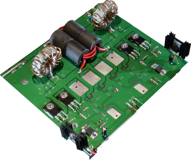
OK, so the project is finally completed and I’ve done some tests. Of course, this project will never be 100% complete. The transmitter does work and at a high efficiency of 95%, but only below 5MHz. It should work great for the 80 meter and 160 meter ham bands, but my goal of 40 meters (7MHz) has not yet been met.
I need to do more work to determine the weakest link. It is likely that it has to do with the drivers. I need to take some measurements with a scope to determine the problem. I will keep this post updated with the changes I make to get it working on 40m.
So far, there is one notable change I made that differs from the schematic I posted in my earlier post. I ended up needing 18V into the drivers rather than 8V. So I upgraded the power supply to 24V and used a 13.7V reg for the control board and then the two 18V regs for the drivers.
My efficiency is now as follows:
| Frequency | Voltage | Amps | RF Watts | Heat Watts | Efficiency |
|---|---|---|---|---|---|
| 3MHz | 13.8V | 4.0A | 50W | 5.2W | 90.6% |
| 7MHz | 13.8V | 3.4A | 32W | 14.9W | 68.2% |
| 3MHz | 28.1V | 7.5A | 200W | 10.7W | 94.9% |
| 7MHz | 28.1V | 6.67A | 140W | 47.4W | 74.7% |
| 3MHz | 48V | 14A | 640W | 32W | 95.2% |
| 7MHz | 48V | 12.7A | 410W | 198W | 67.4% |
Update 02/27/19
I’ve done more testing and have concluded that it is not possible to do more than 5 MHz (5.5 MHz tops) with this PCB. The TC4452 drivers are just not going to do it and I can’t change them out for something better as the ‘better’ ones use a different pinout. Looking on a scope I can see the rise time on the DDS module to be about 7ns regardless of frequency (3 – 8 MHz). However, looking at the output of the TC4452(s), it is about 20ns rise and 25ns fall time. I think this is too large for it to be efficient at 6 to 8 MHz. Rise time is critical for these types of amplifiers because the MOSFETs operate at the highest efficiency when they are fully on or off. If they are part way on (during the rise time), they generate a lot more heat.
Another thing I tested to try to improve the efficiency was changing the duty cycle to 40%/60% rather than the normal 50%/50%. This apparently reduces the chances of cross conduction (the time when both sets of MOSFETs are on at the same time). We don’t want both sides on at the same time because this is a push pull amplifier. It will result in poor efficiency and possibly popping a FET if there is too much cross conduction. After changing the duty cycle to 40/60 (ie 40% on time and 60% off time for each side respectively), the efficiency of the amp went up to 80% from the original 74% shown above. That is not nearly enough of a change to call it ‘working’ at 7 MHz though.
In order to get good efficiency at 7 – 8 MHz, I am going to have to redesign the board. Two alternative drivers that should work better at these frequencies are the IXDD614 and the NCP81074A. In addition to changing the drivers, I will use one driver per FET. The NCP only comes in a surface mount package, so I am a bit concerned with heatsinking, but I have seen this one used in a picture. I think it will work well.
So stay tuned. It will probably be a while until the next update here because I have to design and order the new PCB, but I’ll be sure to update on how that one is working at the higher frequencies.


 Welcome to the first post of DosaidSoft.